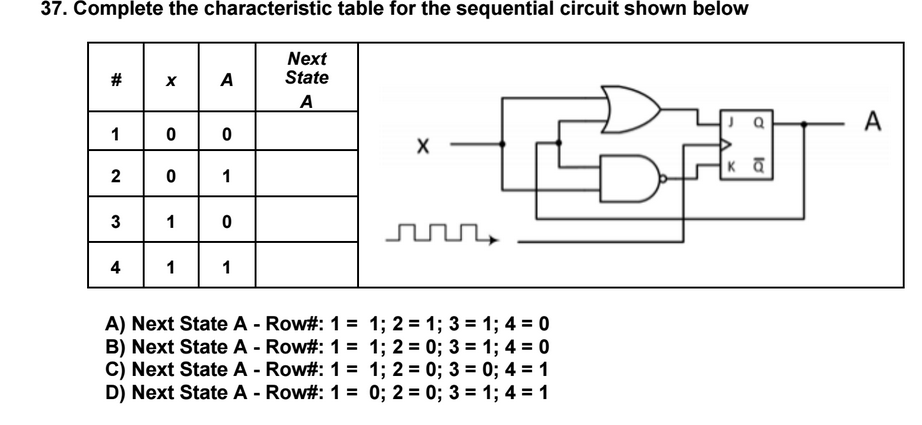
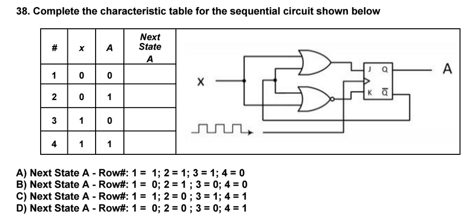
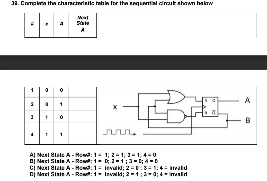
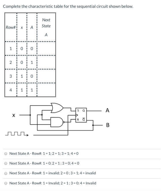
Complete the Characteristic Table for the Sequential Circuit Shown Below.
2 0. A sequential circuit has one flip-flop.
Solved Complete The Characteristic Table For The Sequential Chegg Com
Review the Sequential Circuits homework.

. Use Boolean Algebra to show how the circuit in problem 2 is equivalent to one of the fundamental circuits used to build CPUs. Complete the characteristic table for the sequential circuit shown below. This circuit is clocked.
C Draw the corresponding state diagram. And one output z is specified by the following next-state and output equations. Complete the truth table for the following sequential circuit.
At1 xy xA Bt1 xB xA z B a Draw the logic diagram of the circuit. The following characteristic table describes a storage element A-B 1 Write the characteristic equation for the storage element A-B. Complete the characteristic table for the sequential circuit shown below Next State A - Row.
And all flip flops are positive-edge triggered. State Diagram State Table Sequential circuit components Flip-flops Clock Logic gates Input Output. Two inputs X and Y.
Current state State after next clock pulse B A0 A1 A0 A1 0 0 0 0 0 1 0 1 0 0 1 1 1 0 0 1 0 1 1 1 0 1 1 1. The characteristic table shown below contains two rows where the next state for A and B is incorrect for the accompanying circuit. 2 0.
4 1 The characteristic table shown below contains two rows where the next state for A and B is incorrect for the accompanying circuit. 4 0 C Next State A - Row. While designing a sequential circuit it is very important to remove the redundant states.
Complete the characteristic table for the sequential circuit shown below. 2 13 0. A Next State A - Row.
Complete the characteristic table for the sequential circuit shown below. 4 0 B Next State A -. Q1Q2Q3 Q1 1Q2 1Q3 1 Z1Z2 X1X2 5 00 01 11 10 00 01 11 10 011.
Introductory Circuit Analysis 13th Edition 13th Edition. Two inputs x and y. Circuit State Diagram State Table State diagram.
Fill in the characteristic. A n B n Q n Q n1 0 0 0 0 0 1 0 1 0 0 1 1 1 0 0 1 0 1 1 1 0 1 1 1 What fundamental circuit has the same characteristic table. х A 3 Q B DQ J K D A t1 B t1 Clock 1 2 3 X 0 0 0 0 1 1 1 At 0 0 1 1 Bt 0 1 4 0 1 0 1 5 6 0 0 1 1 7 0 8 1 1.
0 1 3 1 0 4 1 1 A Next State A - Row. The output is 0 labelled RThe name SR stands for Set-ResetThe logic symbol for SR flip flop is shown. Consider the following circuit involving three D-type flip-flops used in a certain type of counter configuration.
SR flip-flop is one of the fundamental sequential circuit possible. Design a Mealy sequential circuit which has one input X and two outputs Z1 and Z2 which. A scan path test circuit of the type shown in Figure 10-8 has three flip-flops two inputs and two outputs.
First complete the characteristic table. 4 0 B Next State A - Row. Next State A A 4 1 A Next State A - Row.
Your answers should show the states of A0 and A1 after the next clock pulse. Synchronous Sequential Circuits Verilog Blocking vs. Complete the characteristic table for the sequential circuit shown below.
Where 00 A 01 B 10 C 11 D Derive the state diagram from the state table. Complete the characteristic table for the sequential circuit shown below. You MUST pick one row in the table to demonstrate how you obtain the values of J K D At1 and Bt1.
10 Elec 326 19 Sequential Circuit Analysis Derive the state table from the transition table. And all flip flops are positive-edge triggered. Complete the characteristic table for the circuit shown below.
Complete the characteristic table for the sequential circuit shown below. See problem 1 for the definition of a JK flip-flop Consider the sequential circuit shown below. Consider the sequential circuit shown below.
Next State A - Row. Since in Moore state machine model the output depends only on the present state the last column has only output. However there is a component missing.
The last column has only output. Next State х A A Q A 1 0 0 х Κ Ο 2. Circuits with Flip-Flop Sequential Circuit Circuit State Diagram State Table State MinimizationState Minimization Sequential Circuit Design Example.
The output is 1 and is labelled S and other which will Reset the device ie. One row of the state table of the sequential circuit to be tested is as follows. It consists of a full-adder circuit connected to a D flip-flop as shown below.
Modify the four-bit ripple carry adder below to perform 2s complement addition when a control signal X 1. Choose the correct answer and show all your intermediate steps to receive full points. Complete the characteristic table for the circuit shown below.
56 A sequential circuit with two D Flip-Flops A and B. X y z xyz xz xyz The complement F of F x y z x yz y x y z not simplified is. 1 Introduction 2 Voltage And Current 3 Resistance 4 Ohms Law Power And Energy 5 Series Dc Circuits 6 Parallel Dc Circuits 7 Series-parallel Circuits 8 Methods Of Analysis And Selected Topics dc 9.
Answers should include the states of A 0 and A 1 after the next clock pulse. The table shown below is the state table for Moore state machine model. Q X0 X1 AA B0 BB D0 CC A1 DD C1 Q Z Elec 326 20 Sequential Circuit Analysis 4.
This circuit is clocked. B List the state table for the sequential circuit. And one output S.
B a First complete the characteristic table. If at some instance prior to the occurrence of the clock edge P Q and R have a value 0 1 and 0 respectively what shall be the value of PQR after the clock edge. X y z y x y z The logic circuit below is supposed to be designed to produce the truth table also shown below.
This simple flip flop is basically a one-bit memory storage device that has two inputs one which will Set the device ie.
Solved Complete The Characteristic Table For The Sequential Chegg Com
Solved Complete The Characteristic Table For The Sequential Chegg Com
Solved Complete The Characteristic Table For The Sequential Chegg Com
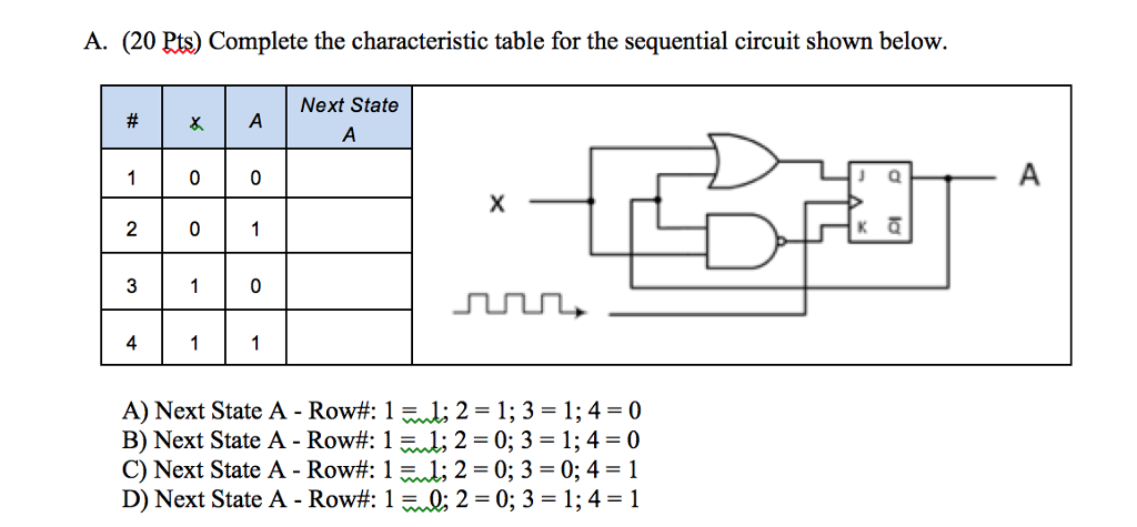
Solved A 20 Pts Complete The Characteristic Table For The Chegg Com
No comments for "Complete the Characteristic Table for the Sequential Circuit Shown Below."
Post a Comment